As in any other case, Symbols are used to specify and better understand the information we want. The welding symbols are used to plot designs onto a plane and used in engineering (industries). It helps the engineer to do work in a practical and precise way, obeying specific rules.
American Welding Society (AWS) established a set of basic symbols for welding and its application in the industry. The welding symbols are used to report a series of instructions graphically.
Lengthy explanations are not needed to understand them. Necessarily, to understand and graph the plane’s designs, we need to know what types of symbols are basically used.
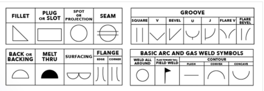
Common Weld Symbols

The table presents some of the most commonly used welding symbols.
These are some of the supplemental weld symbols. The article below covers others as well and in more detail.
- Fillet – The most used weld.
- Groove – Second most used. It usually involves preparing the edge pieces to form one of the groove weld shapes like V, bevel, U, J, Flare V, Flare bevel or no preparation at all with square edges to form a square groove.
- Plug/slot – These are welds used to form overlapping joints using holes in which welds get deposited.
- Flange or edge welds.
- Seam welds – They are made using high heat input and are made in linear form.
- Spot welding – Done similarly to the seam except that these welds are done in a singular spot.
- Back/Backing – They use the same symbol but are different. The backing weld is deposited before the actual weld in the groove. Something like a pre-weld. The back weld on another hand goes after the actual weld. Something like giving the weld a good back.
- Melt-thru – Indicates that the root of the weld needs to be reinforced.
- Surfacing – Specifies the welds that are made over the entire surface of the piece.
- Backing bar – Designates the backing bar to be used on the back of the weld. If it has R in it, it should be removed after welding.
- Spacer – This symbol indicates the type and the dimension of the spacer that is inserted between the welded pieces.
- Weld all around – It signals that the weld is to be made over the entire circumference.
- Flag symbol – Field weld/Made on site.
- Contour – These symbols designate the final weld end product contour.
Learning all the welding symbols may be hard as there are a lot of them. However, you should know how to read a welding chart as it is much more important than trying to memorize all of them by heart. The most important symbols that you do have to memorize are the fillet weld symbol and the groove weld symbol.
You are more than likely going to come across welds on engineering and fabrication drawings. These are a set of symbols that describe the weld, the weld leg size, as well as giving processing and finishing information. The joint is the basis for reference for welding symbols.
The complete set of welding symbols is published by the American National Standards Institute (ANSI) and the American Welding Society (AWS).
Elementary Symbols
Elementary symbols are usually added to the reference line. Their purpose is to indicate the type of weld. You can usually find them marked at the midpoint.
These symbols are combined so as to convey certain configurations. If the symbols are not clear enough, meaning that they cannot provide the information needed, there may be a drawing of the cross-section of the weld with its dimensions. Symbols for double-sided butt welds are drawn on the opposite side of each other.
Complementary Symbols
Complementary symbols exist as additional information. Their purpose is to add info about something like the shape of the basic weld and how it should be made.
Structure Of Welding Symbol
1. Arrow and reference line
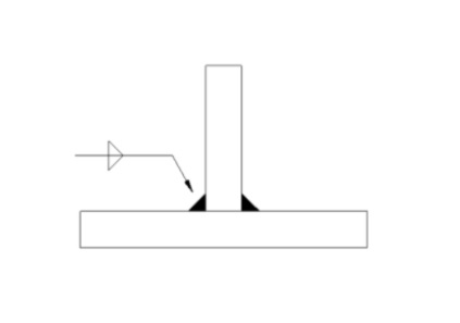
This is a quick way to know you see a weld symbol. The arrow points to the joint where the weld will be placed, while orientation and weld type information is given along the side of the arrow or reference line.
2. Type of welding
Along the reference line’s sides, a symbol representing the joint design or the finished weld indicates the type of weld, using commonly used groove weld symbols, including V-butt joints, joints taper, and fillet welds. Circles and spot welds indicate spot welds by a circle crossed by two parallel lines.
3. Positioning or orientation of the weld.
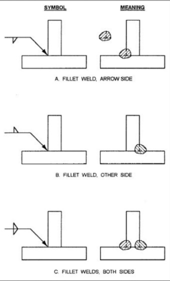
If the weld type symbol appears below the reference line, the weld should be on the same side of the connection as the arrow. If it is above the reference line, it is on the opposite side of the joint. If the symbol repeats both above and below the reference line, both sides of the joint should be welded.
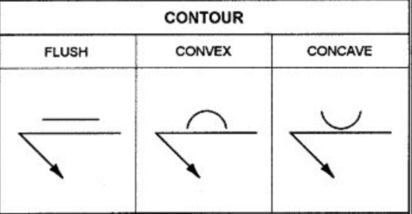
4. Weld the outline
Whether a weld should be flush, concave, or convex is indicated by a line along the icon representing the type of weld. A straight line indicates a flush weld, and concave and convex welds are indicated by curved lines.
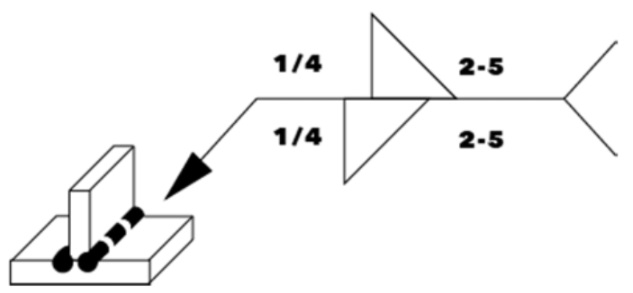
5. Size of the weld
The numbers on either side of the base weld symbol indicate the size. The number to the left of the weld symbol indicates the width and the number to the right indicates the length.
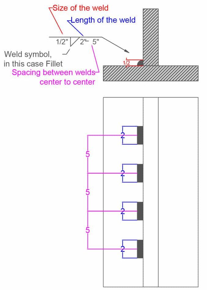
Sometimes there are two numbers to the right of the symbol, separated by a hyphen. When you do this, there will be multiple welds, as is the case with intermittent fillet welds, and the second number indicates the distance between the centers of each individual weld.
For a fillet weld, if the fillet symbol is displayed both above and below the reference line with the same number to the left at each point, the welder should create an equilateral weld.

6. Additional symbols
One of the most important additional pieces of information from an entrepreneur’s perspective is a small flag along the reference line. This indicates that the weld is an on-site weld (i.e. a weld that must be done on-site).
More details on the type of welding or how it is performed can be found at the end of the arrow. (If no additional information needs to be provided to the welder, the glue is usually left out.)
Often, this additional information is in the form of an abbreviation, which in the United States is based on reference codes from the American Welding Society and indicates a specific welding process. For example, FCAW stands for Flux-Cored Arc Welding, while SMAW stands for Shielded Metal Arc Welding (both of which are commonly used in construction).
Although they are less likely to be encountered in the United States, you can also find numbers at the end of the lean. In this case, the ISO codes of the International Organization for Standardization (136 corresponds to FCAW; 111 corresponds to SMAW).
Location Of Elements Of A Welding Symbol

The above image shows how a typical welding symbol may be constructed. This may differ a bit from region to region but this is the way it is done most of the time. This graph is the most important one to have on you when reading the symbols or to memorize what each of its parts means. In time you will memorize all of it and it will be like second nature to you.Now, let’s see what all of the above-shown elements mean:
- The Groove design – There are so many different groove designs that you can use. Any welding symbol is not complete without a specific symbol for what method of joining pieces together you should use. Most of the time you will be working with some type of a groove or a fillet weld but there are other symbols that can be used here too as you will learn soon.
- The Weld size – These dimensions are very important because they are directly responsible for the joint’s ability to withstand the needed load. The S (size) is mostly used with the fillet and groove welds and so is the E (Effective groove size or Effective throat). The size represents the leg size of the weld in fillet welds. It also represents the depth of preparation in groove welds. The E is used to designate the actual depth of penetration in groove welds.
- The Lenght and Pitch of weld L and P – These numbers are not common but there are definitely instances when they are needed. In certain fillet welds, it is necessary to leave some parts unwelded to help with deformation and crack avoidance. That is why the number L specifies the actual welding length and the number P the pitch or spacing between the welds (center to center). This is also used on other types of welds like stud and plug welds but in a bit of a different way. All of this will be shown in detailed examples below.
- Root opening R – This one is rather simple. Root opening is a small gap between two separate metals that you are welding together. This is done in various welds and most commonly in groove welds. Root opening can also have a backing bar that is to be removed or kept after the weld is done.
- Bevel angle A – The bevel angle information tells you what angle needs to be made between the two beveled pieces or between one beveled piece and another that has a straight edge. Or in other words between sides of a V groove (double bevel) or a single bevel joint. It is an important metric that must be done according to the engineer’s demand.
- Contour (presented above the angle number on the symbol diagram above) – This information is given in a graphical form as a straight line, convex or concave shape. It represents the contour of the finished welded bead shape after the manipulation process that produces the desired contour. It is often that two joined metal parts need to be a part of a more complex structure and a weld bead can be a problem. That is why it is necessary to produce the contour the symbol demands. This leads us further to…
- Finishing F – In order to make the desired contour, you will need to know what process to use. Achieving the desired contour is often done just by using a grinder. There is a symbol for that as you will learn later in the article but there are also other ways of getting the contour like gouging or machining and others.
Numbers In Welding Symbols
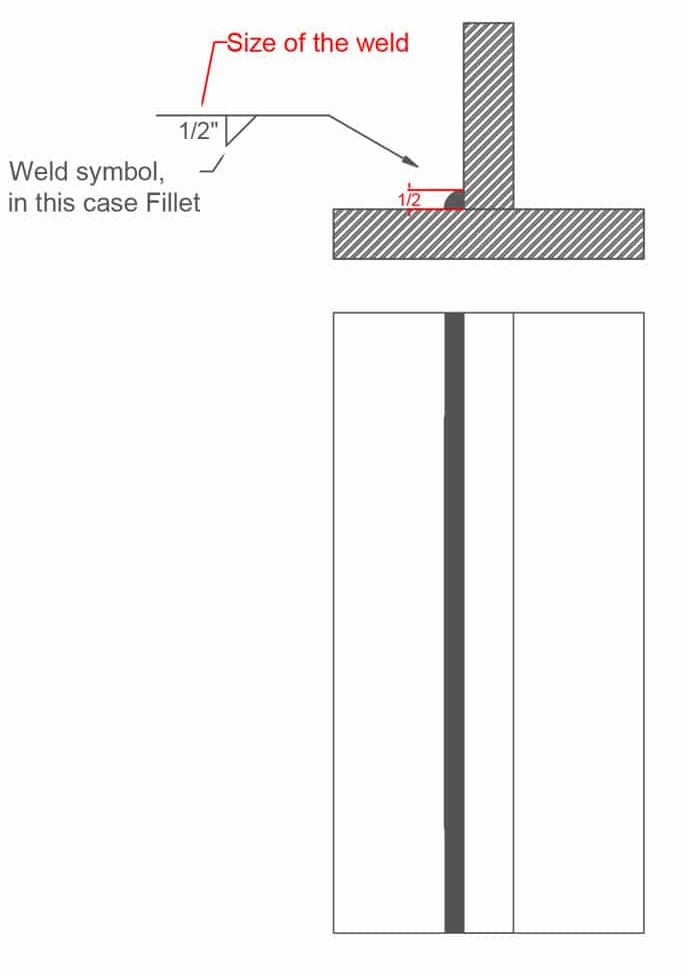
1. Fillet Example – Length of Weld Not Defined
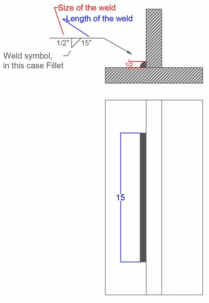
2. Fillet Example – Length of Weld Defined
3. Fillet Example – Length of Weld and Spacing Defined
Consumable Insert
If an insert is used within a welded joint that needs to become a part of the weld it is designated using the consumable insert welding symbol. This symbol should have a specified shape, size and material. Similar to the two above, this symbol is also placed on the opposite side of the groove weld symbol.

Back Weld Example

Backing Weld Example

Application of Welding Symbols
The Reference Line. In any weld design, you start by drawing a horizontal line called the Reference Line. From this line, the other symbols will be added to complement the design.
When we proceed to do the welding, the procedures will be placed below or next to the reference line. Simultaneously, an arrow will indicate the place or “joint” where the welding will take place. The joint is the place where you proceed to weld.
An arrow indicates the two sides of a “joint.” There are some designs where we find two hands drawn. One opposite the other, depending on how you want to put together the engineering work. Each arrow represents an optimal option for welding.
Complementary welding symbols. They are those that complement the welding work. The emblem will abbreviate specific instructions that are necessary for the graphic on the plane.
The flag where it is attached to the Reference Line. A banner on the reference line indicates that the welding will be done in the field or while it is being manufactured.
The empty Circle between the reference line and the arrow. This symbol is used to indicate that welding must occur around or around the entire Circle.
The tail”. Add additional information about the plan. It is the place where communication that helps the welding job will be placed.
Welding Symbols Recommendations
- Your reference line may have different directions. When your weld symbol is below your reference line, the part to weld will be on the side of the joint where the arrow is pointing. If, on the contrary, it is above the reference line, the weld will be made on the opposite side of the joint where the arrow points.
- Graph the direction of the arrow. The arrow can indicate different directions, as we have said. The broken hand may be found, pointing you in various directions.
- Proceed to add dimensional dimensions to the right side of the symbol. The first dimension to be made will be concerning the length of the weld. The second additional dimension will show you the distance between the weld centers. There are a variety of signs to complement the design according to the need of the engineer.
Welding Symbols Precautions
- The symbols in welding simplify a series of instructions in a plane, and they would cover too much space, making heavier understanding.
- Each symbol or graphic represents a design to follow from a job to be done.
- The “tail” can be omitted when no reference line is used. It has no particular information.