It’s easy to slip into a designer’s sphere and not spend the time to understand the business that is building your design.
Engineering, as well as possible across all industries, there are a lot of words to be packed, and most people don’t take the time to comprehend the impact they have on the outcomes.
17 Articles
Reviewed
115 Hours of Research
18 Experts Interviewed
280 Reviews Analyzed
The design of a welded joint is not an easy job, and often an improperly designed joint can lead to a poorly constructed product.
The word weld is a term that refers to the welding process and the kind of weld joint filler metal, heat-affected zone and material temper, porosity shrinkage, distortion structural integrity, etc.
The majority of all of the above terms and concerns will be handled by the manufacturing plant involved in the project; however, the design engineer needs to know the procedure.
The design engineer should also focus on the next higher assembly, interface/interference analysis, type of weld joint that will comply with requirements while reducing preparation time and potential fixture development, machinability, environmental effects on the part, etc.
The design of a welded assembly or part that is to be used by the public should adhere to strict standards set to ensure safety by organizations and governments around the world.
These standards assure designers and manufacturers by providing simple-to-follow welding guidelines for well-engineered joint construction.
While designers must select the appropriate material for the job and conduct a subsequent structural analysis of the item as per the standard,
it is feasible to create welded joint designs assuming that engineering principles will not be lost between the groups involved.
Welding Standards
Like other reports on standards, specifications and standards for welding are not to be regarded as the absolute standard of best practice; instead, they are merely the practice of engineering and science is widely used with results and experience to prove the claims.
Standards are a great resource to utilize and learn from because they let you understand the viewpoints of every person involved in designing or manufacturing a line.
When you know the guidelines and their implications, you’ll be able to make better-informed decisions regarding the design of welded joints instead of simply saying “weld according to AWS d17.1,” as well as accidentally creating a component that will become more expensive or being constructed poorly by a manufacturing facility.
Here are the most commonly used standards throughout America.
The United States of America, but there are many other options, all of which are native to a specific country or company.
ASME Codes –ASME Codes American Society of Mechanical Engineers includes welding specifications integrated into specifications for manufacturing and design.
AWS Standards — American Welding Society Code standards that serve as guidelines to welding in general and niche subjects ranging in the range of AWS D1.2 (Structural aluminum welding) and up AWS D18.3 (Hygienic apparatus welding).
ISO Standards — International Organization for Standardization — thousands of comprehensive guidelines and standards that address weld processes and specifications and classifications for the vast majority of current methods.
Other available weld standards are specific to particular regions or countries like those of Australian standards (AS/NZS), Canadian Standards Association (CSA), European Union (CEN), British Standards (BS) and many more—selecting a standard for designing to will depend on the customer’s needs and preferences to have a greater standardization.
Each of these organizations is similar in standardization and information, and, in some instances, they are written on one another.
This page will concentrate on the AWS standards documents to keep all of the information in line.
Engineering Drawings
The aim of engineering drawing weld symbols can be to establish the possibility of communicating between engineers, designers, and manufacturers. Weld symbols on drawings must be understood by all involved in the manufacturing and design process and shop floor employees.
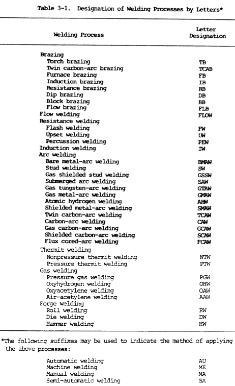
Using a single leader-line-arrow symbol, a design engineer can convey the kind of weld and joint preparation, the length or the depth weld and the location of the weld and the number of welds and spacing and even direct to notes or other locations that have identical joints.
ASME Codes
The ASME provides codes for over 500 different procedures. These standards typically address:
- Performance test codes
- Pressure technology
- Nuclear technology
- Standardization
Despite the wide range of different codes, the ones you need to know the most are:
Boiler and Pressure Vessel Codes
The ASME has been providing Boiler and Pressure Vessel Codes (BPVC) since its early formation in 1914. The codes in this section provide requirements for the construction of power, electric, and miniature boilers, as well as high-temperature water boilers, heat recovery steam generators, certain fired pressure vessels, power boilers used in locomotive, portable, and traction service.
This section covers the rules pertaining to the use of ASME Certification Mark and V, A, M, PP, S, AND E designators. These rules apply to boilers that generate steam or other vapors at pressures exceeding 15 psig, as well as high-temperature water boilers that operate at pressures that exceed 160 psig or temperatures that exceed 250 degrees F. Lastly, it also includes rules pertaining to superheaters, economizers, and other pressure parts connected directly to the boiler without intervening valves.
The sections included in the boiler and pressure vessel codes include:
- I – Power Boilers
- This section includes the requirements for boilers fabricated by welding.
- II – Material Specifications
- This section includes four subparts:
- A – Ferrous material specifications
- B – Non-Ferrous material specifications
- C – Specifications for welding rods
- D – Properties
- This section includes four subparts:
- III – Nuclear
- Division 1 – Rules for the construction of Nuclear Facility Components
- Division 2 – Code for concrete reactor vessels and containment
- Division 3 – Containment systems for storage and transport packaging of spent nuclear fuel and high-level radioactive material and waste
- IV – Heating Boilers
- This section includes the rules for constructing heating boilers.
- Heating boilers included:
- Steam heating boilers
- Hot water heating boilers
- Hot water supply boilers
- V – Non-Destructive Examination Methods
- This section provides non-destructive examination methods intended to detect surface and internal discontinuities in the materials, welds, and fabricated parts.
- VI – Rules for the Care and Operation of Heating Boilers
- This section includes rules for the care and operation of heating boilers.
- VII – Care of Power Boilers
- This section includes rules for the care and operation of power boilers.
- VIII – Pressure Vessel and Tank Code
- This section includes three subsections:
- Part A – General pressure vessel information
- Part B – Requirements pertaining to the methods of fabrication for pressure vessels
- Part C – Requirements pertaining to the different classes of materials
- This section includes three subsections:
- IX – Welding and Brazing Qualifications
- This section includes the requirements for welding procedure specifications and the requirements for procedure qualification records.
- It also includes requirements for:
- Tackers
- Welders
- Welding operators
- Brazing personnel
- X – Fiber-Reinforced Plastic Pressure Vessels
- XI – Rules for in-service inspections of nuclear power plant components
- XII – Transport Tanks
Other Codes To Know
Besides the BPV codes provided by the ASME, there are other important codes to know. The following codes include the requirements for the design, materials, fabrication, erection, testing, and inspection of:
- ASME B31.1: Power Piping
- The different power piping includes:
- Electrical generation stations
- Industrial and institutional plants
- Central and district heating plans
- District heating systems
- The different power piping includes:
- ASME B31.2: Fuel Gas Piping
- The different fuel gases used in piping include:
- Natural gas
- Manufactured gas
- Liquefied petroleum gas-air mixtures
- Liquefied petroleum gas in the gaseous phase
- The different fuel gases used in piping include:
- ASME B31.3: Process Piping
- This code pertains to all fluids, including:
- Raw, intermediate, and finished chemicals
- Petroleum products
- Fluidized solids
- Refrigerants
- Cryogenic fluids
- This code pertains to all fluids, including:
- ASME B31.4: Liquid Transportation Systems for Hydrocarbons, Liquid Petroleum Gas, Anhydrous Ammonia, and Alcohol.
- Aside from those mentioned, these liquids include:
- Crude Oil
- Condensate
- Natural Gas
- Natural Gas Liquids
- Liquefied Petroleum Gas
- Carbon Dioxide
- Liquid Alcohol
- Liquid Anhydrous Ammonia
- Aside from those mentioned, these liquids include:
- ASME B31.5: Piping Refrigeration
- This code provides the requirements for the materials, design, fabrication, assembly, erection, testing, and inspection of refrigerant and other coolants.
- ASME B31.8 Gas Transmission and Distribution
- The different gas transmission and distribution systems include:
- Gas pipelines
- Gas compressor stations
- Gas metering and regulation stations
- Gas mains
- Service lines
- The different gas transmission and distribution systems include:
- ASME B31.9: Building Service Piping
- This code provides the rules for the following building piping:
- Industrial
- Institutional
- Commercial and Public
- This code provides the rules for the following building piping:
There are hundreds of welding codes provided by the ASME, but the codes we provide here are the ASME welding codes you need to know because they are the most common in the industry.
Welding codes infographics

How To Interpret The Weld Symbol ?
The weld callout (a collection of weld symbols that informs the person who interprets the whole welding joint welding process) comprises weld symbols and any additional information pertinent to the process, all of which are standardized on an arrow leading to the leader.
The arrow links to the weld callout to the other end of the joint, which is weld.
The longer line contains all the elements that define the joint’s preparation and the weld dimensions, location, etc., requirements.
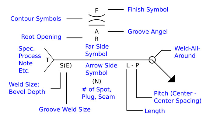
The split lines at the ends are optional, referred to as the tail, and can be accompanied by any other specifications or information about the reference.
Below is a full representation of an example of a weld symbol callout based on AWS standards. AWS standards for the location of data. The information is usually identical between AWS standards as well as ISO standards. However, the numbers could be displayed in different areas of the arrow leader.
Below are some examples of weld callouts that use the previous weld symbol diagram for illustration. Some minor differences are the locations of the finish and contour symbols and the field flag symbol.
- The end symbol is usually found along with the contour symbol right under or adjacent to it—the weld symbol.
- The groove angle and the root opening are located on the opposite side of the weld symbol it is connected to.
- The field flag signifies that the weld will be finished on the part either during or following installation (in out in on the upper assembly).
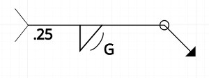
Example 1 illustrates the .25″ fillet weld that is located on the nearest side (or the arrow-side) of the joint. The weld is referred to as “all-around,” indicating that the weld on the joint remains continuous until it joins to itself. It is then contoured using a grinding pad. Weld is then shaped using an abrasive pad.
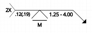
The 2nd example shows an example of a .12″ V-groove weld with a .19″ actual dimensions (or penetration) located on the far side of the joint.
The weld is continuous across the entire joint, with a width of 1.25″ and an angle (center space to center) that is 4.00″. Welds are welded then flat-machined to the surface of the member.
The weld features a “2X” indicator at the callout’s tail, indicating that the whole weld callout is utilized in two places with common joints.
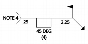
Example 3 illustrates an example of a .25″ plug weld with an angle of countersink of 45 degrees, located on the opposite side of the face of the member. The total number of welds is four, with a center-to-space between them of 2.25″.
This weld is also recommended to be carried out in the field of the uppermost level assembly instead of as an independent part. The end of the callout refers to note four which specifically addresses the weld.
Designing using Weld Symbols
The design of the weld specifications on a component may be based on strength, corrosion resistance, EMI protection specifications, environmental requirements, anticipation for movement of the material, and more.
Fixturing
Precision parts will likely have strict GD&T limits, eventually creating custom fixtures to facilitate this welding process. Reducing the tightness requirements to anticipate the material’s movement during weld can greatly cut manufacturing costs.
Weld sizes
Minimum weld dimensions differ for different types of welds and standards. AWS, the structural welding codes should be considered along with customer-specific regulations, if needed, when creating the weld joint.
In all instances, it is recommended that a structural analysis parallel to the design and other tests must be performed to ensure that the details in the standards are applicable to the project you are working on.
For instance, the minimal fillet weld size for a welded steel joint when the thickness of the steel does not exceed .25″ will be .125″ (AWS D1.1: Structural Welding Code – Steel 5.8). 5.8).
Corrosion
Corrosion is a major factor in the longevity of a product and repair cycles. In many instances, even with a match filler metal in the weld joint’s heat-affected area is likely to develop corrosion at a different speed as the base material because of the various chemical composition.
Welding Strength and Quality
A structural analysis must be conducted for parts that are welded. Following the degree of safety considered, the nondestructive test (NDT) might be necessary to ensure that the weld was done correctly.
NDT may include dye penetrant inspection and ultrasonic testing and magnetic particle inspection etc.
Element of the Weld Callout
The weld callout is between the designer’s head and the manufacturing team managing the project. In many cases, the absence of details or misinterpretation of the weld callout could cause significant project delays and result in unanticipated costs while dealing with manufacturing partners.
On the leader line are the weld symbol type, an indication of far-side or near-side and a length and the pitch of weld dimension, contour symbol and end symbol and additional reference details. The tables below explain the different elements.
| Weld Callout Symbols | |||
|---|---|---|---|
| Finish Symbols C, G, H, M, P, R, U Post processing of a welded joint: Chip, Grind, Hammer, Machine, Planish, Roll, Unspecified. |
Contour Symbols ) ( | Post processing to form a concave, convex, or a flat contour. |
Groove Angle A Total angle formed between the groove faces on the weld joint. |
Root Opening R Groove welds – Open space between welded members to help with weld penetration. Plug/Slot welds – Depth of filling. |
| Far Side/Arrow Side Far side – Joint opening on opposite side of feature or plane with respect to leader line. Arrow side – Joint opening leader line is pointing to. Both side weld callouts can be mirrored or staggered in intermittent. |
Weld Size and Bevel Depth S Fillet weld size and bevel/v-groove preparation depth. |
Groove Weld Size (E) Actual depth of penetration of groove weld. |
|
| Number of Spot, Plug, and Seam Welds (N) |
Length L Length of welds if the weld does not span the entire joint or if the welds are intermittent. |
Pitch P Center to center spacing of intermittent or staggered welds. |
Weld-All-Around O Weld or intermittent weld is continuous around a single joint/feature and meets back to the start point. |
| Specifications, Process, Notes, Etc. T Additional information regarding the weld specification, weld wire, changes to the preparation, and other notes. |
|||
Weld Callouts – FAQs
Here are some frequently asked questions regarding weld callouts:
What is ASME Code welder?
The ASME code requires that welders are certified to specific weld procedures used to fabricate the ASME code vessel. Welder certifications must be documented and maintained. A weld map must be generated that shows which welder performed each weld on an ASME code vessel.
What is the ISO standard for welding?
ISO – 25.160. 01 – Welding, brazing and soldering in general.
What are popular welding codes and standard?
Qualification Codes. BS EN 15614, EN 287, EN ISO 9606, BS 4872, ASME Section IX, CAA A8-10.
Regulations/directives. Pressure Equipment Directive (PED)
Fabrication Standards/codes. …
Consumables standards. …
Industry specific codes/standards.
What are the 5 parameters of welding?
Current.
Length of Arc.
Angle.
Manipulation.
Speed.
What is the difference between B31 1 and B31 3?
B31. 1 uses a SIF of up to 1.9 max in stress calculation. ASME B31. 3 uses a complex in-plane, out-of-plane SIF approach.
How many welding standards are there?
The organization has more than 350 welding codes, procedures, practices and standards. The standard D1. 1 (see below) is referenced more than any other code when it comes to steel welding.
What is API in welding?
For those interested in a career within the welding industry, an American Petroleum Institute (API) welding certification can be a valuable addition to welding training and experience.
What does AWS mean in welding?
The American Welding Society (AWS) was founded in 1919, as a nonprofit organization with a global mission: “Advancing the science, technology, and application of welding and allied joining and cutting processes worldwide, including brazing, soldering and thermal spraying.” That is our mission and it’s why we exist.