Insufficient flow of shielding gas causes porosity and weak welds. However, cranking off the valve for shielding isn’t the solution. The problem can be made worse by applying a flow of shielding gas that is excessively high.
The solution is to find the sweet spot and stay between the extremes. In general, when welding mild steel and working indoors with CO2 alone or a 75/25 Ar/CO2 mix, you’ll be able to work with only 10-15 CFH.
However, if you observe any porosity, you should increase the flow rate to the recommended amount of around 20-30 CFH.

But that’s only one situation…
This article will show you how to set the flow rate of gas, the minimum and maximum values and the optimal gas shielding settings for the most common welding materials with the MIG process.
How To Adjust The Gas Flow Rate?
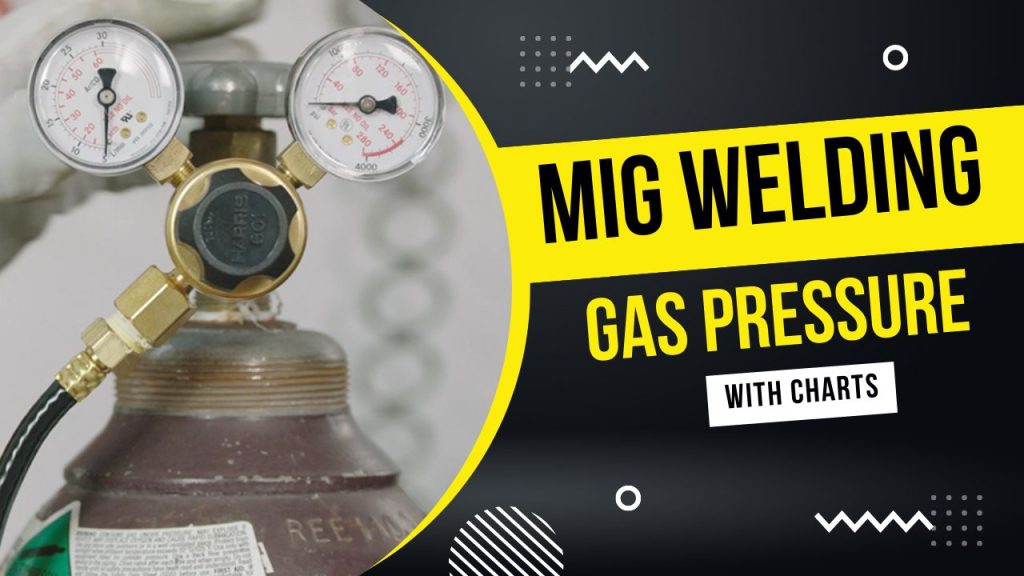
The adjustment of the flow rate of gas shielding is pretty straightforward. Each gas regulator has one valve that allows you to alter your flow. Gas regulators with standard features have two gauges.
The first shows the pressure inside the bottle of gas measured in PSI. The other shows the gas flow rate of cubic feet/hour (“CFH”).
Gas is released from the bottle through the valve while the gauge’s gauge shifts according to the flow rate in CFH.
But, gas regulators of higher quality equipped with a flow meter feature only one gauge, which displays the pressure of the gas bottle.
Instead of a separate gauge, the flow outbound rate is displayed by a specially-designed vertical chamber made of plastic.
The chamber is transparent and has written measurements in CFH and a small ball in the middle. The gas is pumped through this chamber, and the pressure causes that ball to expand. This is the reason they’re referred to in the form of “flow meter regulators.”

As with regular regulators, you can raise the gas flow by closing the valve. However, confirming that the ball is floating at a certain point is more trustworthy.
There’s nothing wrong with standard regulators. However, the springs and needles in the regulator for gas flow might be stuck, or their mechanical performance may decrease.
But, flow meter controllers depend on gravity and pressure to show the flow rate. The measurement does not have the mechanism that is used in regulators.
In essence, the flow meter’s design is based on the fundamental physics of physics and a simple design and not on the complex mechanism of a needle within the pressure gauge.
Our Video Tutorial on MIG Welding Gas Pressure Settings
CFH Or Liters Per Minute?
Cfh is the most popular unit for measuring the flow of gas. However, certain welding gas regulators can measure the number of litres per minute (“l/min”).
We don’t suggest these regulators, as most books and guides on welding provide CFH guidelines.
Is Every Gas Measured Equally?
No. Certain shielding gasses are more potent and heavier than other gasses. This is why you must ensure that the regulator is compatible with the gas shielding you.
For example, if your regulator is calibrated only for argon and you get an incorrect reading when you put it on the gas bottle that shields helium.
It’s not too much of an issue with MIG welding since CO2 and Argon aren’t all that different. But, remember that you will require a regulator specifically designed for your gas to obtain precise flow rate readings.
Pure CO2 Tanks Require Special Regulators
If you’re planning to utilise a gas regulator or flow meter equipped with CO2 gas that is 100% in the tank, you must be aware that it can be frozen due to the low temperature of CO2 created when the gas expands. It is recommended to use an approved CO2 regulator.
The majority of people do not encounter a complete freeze of the regulator. However, if you use it for a long time, you may notice an accumulation of frost around the regulator. In addition, CO2 gas tanks have the CGA-320 connector, whereas most welding gas bottles have CGA-580.
Every CO2 or argon regulator is threaded to CGA-580. To use any gas regulator using CO2 gas bottles, you’ll need this CGA-320 adapter CGA-580.
Best MIG Gas Flow Rates

The most popular metals to be welded using the MIG process are mild steel, stainless steel and aluminium.
Each needs a particular flow rate based on the diameter of the nozzle, the speed at which it travels, the level of mill scale or oxides on the substrate, and the speed of wire feed.
Let’s look at how shielding gas flow influences welding these materials.
Steel
Mild steel is relatively easy to weld. If you’re welding indoors with CO2 alone or a mix of 75/25 Ar/CO2, it will work with only 10-15 CFH. If you notice any porosity, you should increase your flow to 20-30 CFH.
For a better welding speed, please keep it on the upper end of that flow speed and the reverse. Also, the bead’s profile will expand if the feed rate for the wire can is too fast. Wider beads also require more shielding gas flow to cover the melting material completely.
Suppose you are using a nozzle diameter greater than 1/2 inch. The correct distance for shielding is between CFH to 55 CFH. However, most small welding machines utilise MIG gun nozzles with a 1/2 inch—diameter or less.
Stainless Steel
It is a more complicated metal that can be welded. Many factors affect the weld’s final quality, starting with the type of stainless steel and heat management. Therefore, it is not surprising that the flow of gas shields can impact the quality of the weld.
An ideal starting place is between 20 and 25 CFH. Be aware of the surface of the weld and the area surrounding the weld toes. If you notice any porosity, then raise the amount of flow.
A tri-mix shielding agent (i.e. 10 per cent Ar + 85-90% He + 2-5 % CO2) increases the amount of helium as you increase the flow.
Because helium is a heat conductor and stainless steel isn’t so, you can create intense heat spots if you don’t take care to manage your heat input. Therefore excess helium and inadequate heat management could cause carbide precipitation and warping of thin sheet metal.
However, as helium is much lighter than CO2 or argon and CO2, if you don’t have the correct flow rate, not enough Helium will be available, and the metal will be prone to porosity. It’s why it takes some adjustment to ensure the proper shielding gas coverage with the welder you have chosen.
Aluminium
Aluminium conducts heat exceptionally efficiently. To MIG join aluminium, you need to use high travel speeds. This requires a greater shielding gas flow, which is about 30 CFH.
For MIG to weld aluminium will need an inert gas that is completely non-toxic. Absolute argon would be the ideal option for the majority of tasks. However, to weld heavy aluminium, helium can add to the.
Helium increases the transfer of heat and penetrates. However, because helium’s mass is lighter than argon, you might require a significant increase in shielding gas flow rate per the proportion of helium.
For instance, the use of 75 per cent helium with 25% of argon could need an amount of flow up to 50 CFH.
Is There A Minimum Gas Flow Rate?
There is the minimum shielding gas flow rate. However, it is dependent on the material being welded. For aluminium, which we have discussed previously, it is recommended to use a flow rate of less than 20 CFH.
However, when welding mild steel, it is possible to use gas flow shielding as low as 10 CFH successfully.
The flow rate you should use depends on the air dynamics surrounding the welding area. If you are welding outdoors, choose more flow than the one you’d apply inside.
However, if you protect the joint using stands, you could decrease the necessary gas flow rate to shield the joint.
Generally, the best practice is never to use an air flow rate less than 10 to 15 CFH. However, this doesn’t mean the welds will not develop porosity when using a lower flow rate.
For instance, if your joint is very wide and the speed of travel and wire feeding are both high, your weld could become porous due to the insufficient coverage of gas shielding.
Is There A Maximum Gas Flow Rate?
There is an absolute shielding gas flow rate because the powerful flow could cause turbulence and not shield the metal from contamination by the atmosphere.
Due to the venturi effect, the air surrounding the edge of the nozzle is sucked in the gas shielding envelope in case there is a too large flow. Thus the flow rate will depend on the MIG size of the nozzle.
Air can seriously affect the quality of welds, which is why we employ shielding gas to shield the weld pool. However, the shielding gas loses its protection once the air is mixed. The air pockets that have been trapped create the weld to become brittle and porosity.
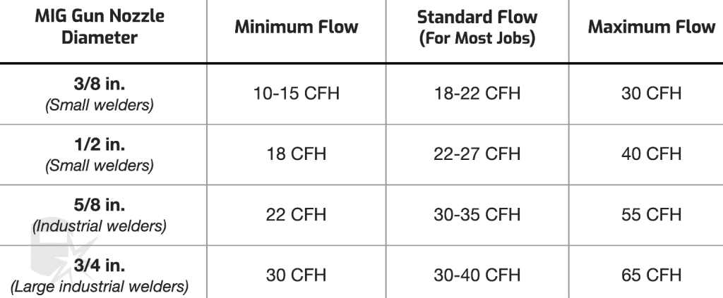
Min & Max MIG Gas Flow Rate Chart
The graph below illustrates the minimum and maximum flow rates for typical MIG diameters. The chart below also shows the nozzle diameters used for argon mixtures and CO2.
Be sure to not go over the recommended maximum levels to prevent air from getting trapped within the gas shielding.

Summary Chart
This table summarises what we’ve discussed in the past to help you determine the flow rate of gas shielding according to the welding material.
This chart offers estimations. The superior flow speed for your welder is based on the configuration of the joint and welding position, the speed of travel, the wire feeding speed, as well as the thickness of the material.

Wrapping It
Determining the ideal point is the key to getting enough gas shielding coverage. It isn’t possible to have either too low or high flow rates since both cause issues.
We’ve provided some suggested beginning points, but you’ll need to work on and refine the flow rate for your specific machine and your technique.
It is the most cost-effective method to make use of the smallest amount of gas that is possible.
Don’t try to force a higher flow since the weld won’t gain from it. Even if the rate isn’t enough to cause turbulence will waste gas if the rates are too much. If you can, lower the rate of flow and only make use of the necessary gas.